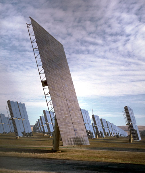
A large array of 1 kilowatt Solar Panels east of San Luis Obispo
California.
A large array of 1 kilowatt Solar Panels east of San Luis Obispo
California.
Introduction
Solar cells convert sunlight into electricity. They can be used to power electric motors.
Material
To Do and Notice
Use the clip leads to connect the solar cell to the motor.
Make a flag out of masking tape on the axis of the motor.
Place the solar cell in sunlight.
Notice how the flag rotates. Note the direction and speed of rotation.
Reverse the leads, connect the red, positive terminal of the solar cell to the other terminal of the motor. Notice that the motor reverses direction.
What orientation of the solar cell produces the maximum rotation rate of the flag?
Use cardboard and aluminum foil to create a reflector to reflect sunlight onto the solar cell and thus create the most rapid rotation rate.
Try holding different filters over the solar cell, what is their effect on the rotation rate of the flag. Try red, green blue and other filters. Try clear acetate smeared with sunblock.
Connect two cells in series with the positive terminal of one connected to the negative terminal of the other. Notice the rotation rate of the motor due to two cells in series.
Connect two solar cells in parallel with the positive terminal of one connected to the positive terminal of the other, and also the negatives connected to each other. Connected these cells to the motor and notice the rotation rate.
Try to light up an LED using solar cells. Depending on your solar cell you may have to connect two or more in series. Simply replace the motor in the above diagram with an LED. However, unlike the motor the LED has a positive and a negative side. The positive side of the LED must be connected to the positive side of the solar cell to light the LED. Try connecting the LEd in both possible orientations. (If one leg of your LEd is longer than the other try connecting the longer leg to the positive terminal.
Use a meter to measure the voltage across your solar cell in full sunlght then again in dimmer light. The meter will have a very high resistance on the voltage scale so this is called the open circuit voltage of the solar cell, Voc. If you do not know which terminal of the solar cell is positive then notice that when the red, or positive lead of the meter is connected to the positive lead of the solar cell the meter will display a positive voltage.
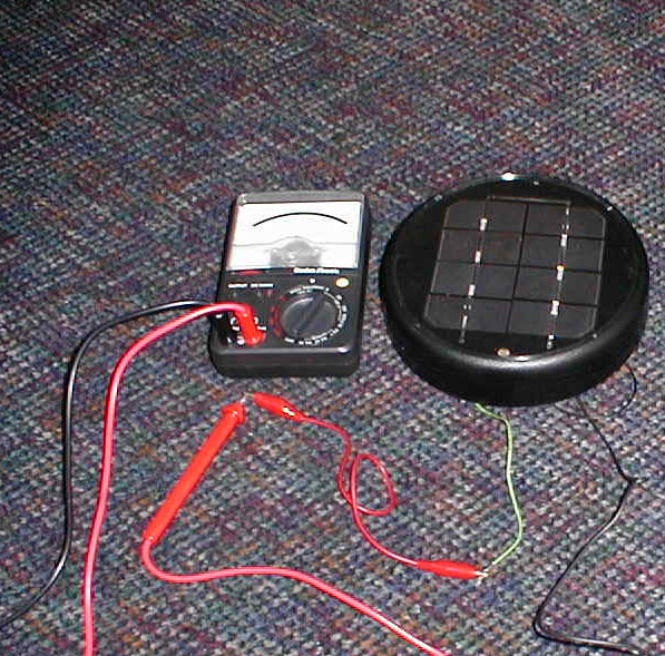
Use a meter to measure the current through your solar cell in full sunlght then again in dimmer light. The meter will have a very low resistance on the current scale so this is called the short circuit current of the solar cell, Isc. When the meter reads a positive electric current then by definition an electric current is flowing into the red or positive lead of the meter. (Note on Current.)
What's Going On?
Level 1.
Sunlight is composed of photons of light. When these photons hit the solar cell their energy goes in to splitting one electron out of one atom of silicon, the silicon atom becomes a positively charged ion or "hole.". These electrons and holes drift toward opposite terminals of the solar cell. The electrons leave the negative terminal of the solar cell move through copper wires of an electric circuit and motors in the circuit causing the motors to turn. The electrons recombine with holes in the silicon near the positive terminal. A single cell of silicon makes a voltage between its terminals equal to that of a 0.6 volt "battery."
Level 2
Solar cells are made from two layers of silicon. One layer has had impurity atoms such as aluminum, which is to the left of silicon in the periodic table and which has one fewer valence electron than silicon. This creates an impure silicon with an electron deficiency, a p-type silicon (think p for positive.) The other layer is "doped" with impurity atoms from the right of silicon in the periodic table such as phosphorus. These atoms have one more valence electron than silicon and are called n-type silicon (think n for negative.)
When the p layer is put next to an n layer a diode is created. The negative electrons can move toward the holes and then recombine with the holes allowing electric current to flow one direction, but if the electrons move away from the holes the current flow stops. However, when a photon hits the silicon the energy of the photon can be absorbed by a silicon atom freeing an electron from the atom and leaving behind a hole. The electron then moves toward the n-type material while the hole moves toward the p type material. This is an electric current which can be used to generate power. (Once again the electric current of electrons moves through the wire and the motor to do work.)
All Levels
Multiple solar cells can be connected in series or parallel.
Series solar cells produce a higher output voltage.
Parallel solar cells do not increase the output voltage but they can produce more electric current.
Math Root
Estimate the efficiency of your solar cells. Measure the power they produce while driving a motor by measuring the voltage across the terminals and the current through the solar cell. Multiply the voltage times the current to get the power of the solar cell Po.
Po = V x I = 0.6 x 0.5 = 0.3 W
Now estimate the power from the sun which hits the solar cell. To do this multiply the area of the solar cell, A, in square meters times the power of sunlight ,Ps, which is about 1000 watts per meter squared, W/m2. If your solar cell is 4 cm by 6 cm then its area is 0.04 m x 0.06 m = 2.4 x 10⁻³ m2. So the power input is
Pi = A * Ps = 2.4 x 10-3 * 1000 = 2.4 watts.
The ratio of the power delivered by the solar cell to the power input from the sun is the efficiency of the solar cell, e, which is usually expressed as a percent.
e = Po/Pi = 0.3/2.4 = 0.12 = 12%.
A conventional electric current is defined as the flow of positive electric charges that produce the same effect as the actual flow in a circuit.In almost all circuits made of wires it is actually the negative charges that flow. The negative charge flow is in the opposite direction to the flow of positive charges that produces the same effect.
|
Scientific Explorations with Paul Doherty |
|
1 November 2003 |